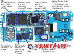
How to Identify Parts and Components on the PCB of
Antenna Point: The point where antenna is connected is called antenna point. It is normally located at the top of the PCB of a mobile phone. Network Section: The section below antenna point and above power section is called network section. Antenna Switch: It is found in the network section. It is ...
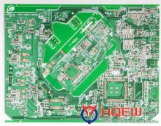
Phone PCBs and Component Layout
As a mobile technician, you get different makes and models of mobile phones for repairs. The basic design of every mobile is same, but the actual component layout and positioning is different in different makes and models. As a technician it is not possible to rememeber the PCB layots of each and eve...
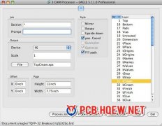
Simple Mobile Detector Circuit
An ordinary RF detector using tuned LC circuits is not suitable for detecting signals in the GHz frequency band used in mobile phones. The transmission frequency of mobile phones ranges from 0.9 to 3 GHz with a wavelength of 3.3 to 10 cm. So a circuit detecting gigahertz signals is required for a mob...

PADs' PCB Layout Guide
A board consists of multiple layers of copper separated by layers of insulating FR4 fire-resistant epoxy. A trace is a wire on a layer of the board. A via is a copper-plated hole that goes through the board to connect layers. The easiest way to build vias is to drill them through the entire board, th...
Common PADs' Components
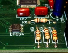
For surface mount resistors and capacitors, 0805 (0.08" x 0.05") packages are recommended. 1206 packages are unnecessarily large, while the smaller packages are more difficult to handle and solder. Voltage Regulators Linear voltage regulators accept a high but somewhat noisy voltage from a source li...
Component Selection
When selecting components, the first goal should be to find parts that meet your performance requirements. Your liaison or advisor may have advice on manufacturers for specialty components. Be sure to pay attention to the supply voltage and logic levels so that components play together nicely. It may...
Overview of PCB for PADs
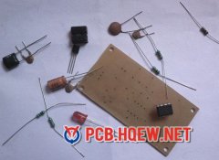
While breadboards are a quick way to prototype a simple circuit, they don’t play gracefully with today’s surface mount components, introduce unacceptable distortion into high speed circuits, are prone to loose wires, and aren’t really a professional way to deliver an end product. Many teams fin...
Materials and Equipment
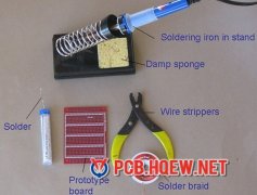
A soldering iron A soldering iron is used to heat the connections to be soldered. For electronic circuits, you should use a 25- to 40-watt (W) soldering iron. Higher wattage soldering irons are not necessarily hotter; they are just able to heat larger components. A 40-W soldering iron makes joints...
PCB Soldering Safety Precautions
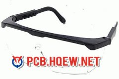
Caution: A soldering iron can heat to around 400°C, which can burn you or start a fire, so use it carefully. Unplug the iron when it is not in use. Keep the power cord away from spots where it can be tripped over. Take great care to avoid touching the tip of the soldering iron on a power line. If...
Common Soldering Problems and Troubleshooting
Solder will not flow. The parts to be joined may be dirty. Remove the solder and clean the parts. The connection looks grainy or crystalline. Parts were moved before the solder was allowed to cool. Reheat to form a good joint. You may need a larger soldering iron to heat connections adequately. ...